
CAN
General Information
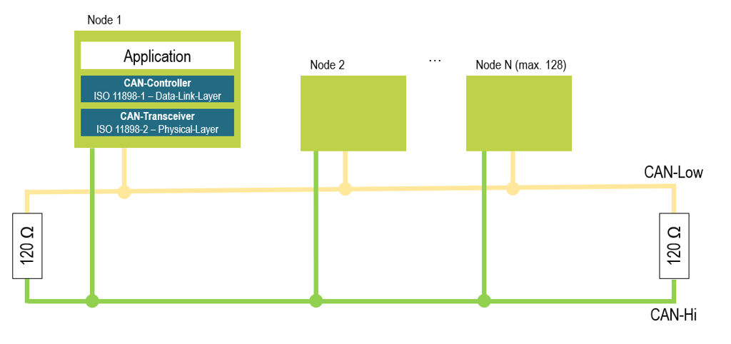
CAN (Controller Area Network) was developed in 1983 by Robert Bosch GmbH and introduced in 1986 in collaboration with Intel. The CAN bus was originally developed for use in motor vehicles. In conjunction with the SAE J2284 and SAE J1939 standards, it is used to transmit diagnostic data and control unit information. It is a serial bus system with multi-master functionality and real-time capability. This allows all nodes to transmit and listen to the bus simultaneously (broadcast). The standard specifies the two lower layers of the ISO/OSI layer model, specifically ISO 11898-1 (Data Link Layer) and ISO 11898-2 (Physical Layer). In vehicle diagnostics, CAN-High and CAN-Low are typically routed through the OBD connector.
The CAN bus is currently still the most widely used bus system in automotive engineering. However, it is no longer used exclusively in this field, but also in industrial plants and other environments prone to interference.
Since 2008, the CAN bus has been the only approved diagnostic interface for emissions-related diagnostics in new vehicles.
Physical Description
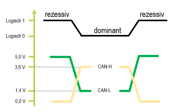
Typically, the CAN bus operates over a twisted-pair two-wire cable, referred to as CAN-High and CAN-Low, which enables symmetrical signal transmission. Often, a ground line (CAN-GND) and a 5V power supply line are included as options. Since a bit is represented simultaneously on two lines with a mutual change in potential, the CAN bus achieves its characteristic immunity to interference. This is a differential signal. Interference affects both wires simultaneously in the same direction. Since both wires carry inverted signal levels, the difference remains constant even in the presence of interference. To prevent signal reflections on the bus, both ends of the bus are terminated with a 120-ohm resistor.
Two different voltage levels on the bus are referred to as a dominant state, which corresponds to a logical 0. Conversely, when the voltage levels are the same, this is referred to as a recessive state, which corresponds to a logical 1.
Transmission Rates
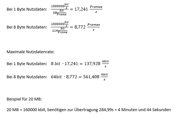
A CAN telegram can carry between 1 and 8 bytes of payload data. Given the complete frame structure of a CAN message (see below), this results in frame lengths ranging from 58 to 114 bits per frame. The transmission rates can therefore be calculated as follows:
Based on the physical structure of a CAN bus described above, and taking into account the required cross-sections and signal attenuation, it is possible to calculate the maximum cable lengths up to which reliable data transmission is guaranteed.
| Bitrate | Cable length |
| 10 kbits/s | 6,7 km |
| 20 kbits/s | 3,3 km |
| 50 kbits/s | 1,0 km |
| 125 kbits/s | 500m |
| 250 kbits/s | 250 m |
| 500 kbits/s | 125 m |
| 1 Mbits/s | 25 m |
The key characteristics of the CAN bus are determined by the management of participant priorities with regard to message transmission and by an error detection strategy. Both are typically provided by hardware chips also known as CAN controllers or CAN cells.
Collision Handling/Arbitration
As with Ethernet, all bus participants may transmit simultaneously at any given time, which can lead to collisions. To prioritize bus access, bit-by-bit arbitration is performed. The message with the lowest identifier (and thus the greatest number of zeros) is granted bus access. All other participants attempt to transmit again when the bus is free. To reliably prevent collisions, a unique assignment of identifiers for all bus participants is required.
Error Detection
The CAN bus specifies certain mechanisms that prevent the bus from being blocked by faulty nodes. To this end, each bus node has a transmit and a receive error counter. Immediately after startup, each node is in the “Error Active” state. If a certain threshold for the error counters is exceeded, the node switches to the “Error Passive” state. In the event of a complete failure of the CAN controller or an extreme accumulation of errors, the node enters the “Bus off” state. This disconnects the node from the bus to avoid interfering with the other nodes. The node can only be brought out of this state by resetting the associated host.
Frame Construction
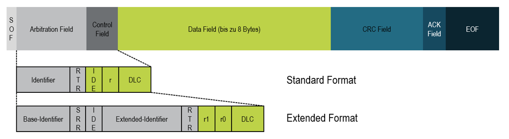
| Term | Description |
| SOF | Start of Frame |
| IdentifierBase-Identifier | Identifier |
| RTR | Remote frame type, used to request data |
| SRR (extended) | Substitute Remote Request |
| Extended Identifier | Identifier |
| IDE | Identifier Extension |
| r, r0, r1 | reserved |
| DLC | Data Length Code, contains the length information |
| Data | Usable data |
| CRC | CRC Checksum |
| ACK | Confirmation of correct receipt of the message |
| EOF + IFS | End-of-data-telegram marker + inter-frame space (distance between frames) |
Do you have any questions about our products or services?
We are here for you! Send us your inquiry using the contact form – our team will get back to you as soon as possible.